Overview
TL;DR We built a miniature linear accelerator powered exclusively by THz radiation, marking the first demonstration of linear electron acceleration using laser pulses. we design a velocity-matched waveguide and accelerate electrons by 7 keV using the longitudinal field component of a modest 10 $\mu$J THz pulse.
The ultimate goal of this project is to develop an end-to-end tabletop x-ray free electron laser (FEL) based purely on optical beams. Such a compact, economical FEL would bring the benefits of rarefied billion-dollar accelerator facilities to the local hospital (medical therapy with X-rays and electron beams) and university laboratory (understanding state transitions in metals, semiconductors, and molecules). This linear accelerator would be integrated with the THz-driven electron gun
Linear accelerators today
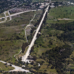
The linear accelerator (linac) is a (typically large) device that accelerates charged particles (seeded by an electron gun) to high speed by subjecting them to strong electric fields along a linear particle beamline. They have many medical and scientific uses, such as generating X-rays or particle beams for medical imaging and radiation therapy, or generating X-rays and high energy particles for condensed matter research. Linacs tend to be expensive (billions) and extremely large (the SLAC accelerator is 2 mi long, as shown in the figure below).
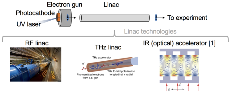
The enormous size and cost of linear accelerators has spawned the development of lightweight alternatives based on commercial lasers, which can generate two orders of magnitude higher electric field than conventional RF sources. Infrared lasers, however, cannot accelerate large bunch charges due to their short wavelength, limiting the amount of coherent X-ray emission which scales as the square of the bunch charge. Laser plasma approaches have achieved GV/m accelerating fields, but with low repetition rate TW lasers and percent-level energy spread and jitter. The figure below shows the where the linac fits in a particle beamline and the available technologies for linacs.
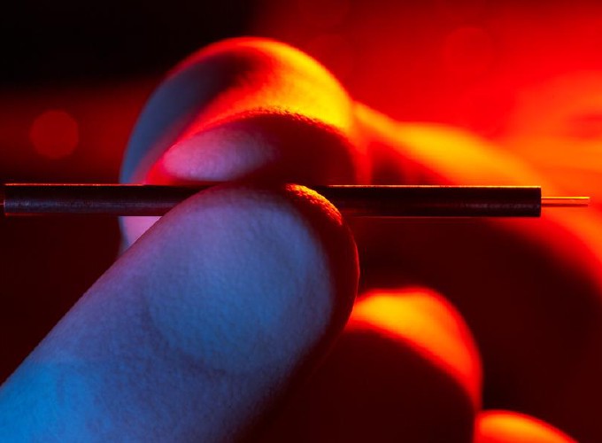
The THz frequency regime strikes the best of both worlds. The wavelength is long enough that waveguides and accelerating structures can be fabricated with conventional machining techniques. The optically-generated THz pulse is intrinsically synchronized with the optical probe pulse ensuring negligible timing jitter. The availability of modest-power commercial lasers makes this technology viable for widespread adoption. Finally, due to the two order of magnitude increase in electric field, THz linacs can be dramatically smaller than conventional linacs. Our prototype linac, for example, is the length of a needle.
A traveling wave structure
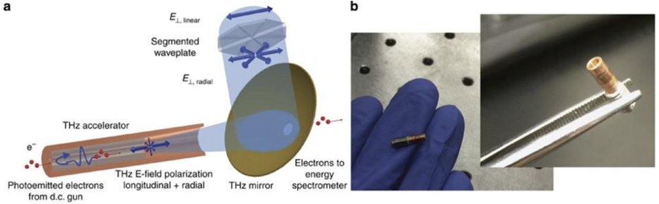
Our experiments were done with a 50 keV electron beam seeded by a DC electron gun. In order to slow down the THz pulse (which is traveling at the speed of light) such that it travels in sync with the electron beam (which is at half the speed of light), we couple the THz beam into a dielectric-coated waveguide which as a phase velocity approximately equal to the electron beam velocity. With the help of a segmented waveplate, the THz is coupled into the TM01 mode, which as a large longitudinal electric component. We time the delay between the electron bunch and THz wave such that the bunch arrives and travels with the THz pulse on an accelerating phase of the field. As the electrons speed up, it begins to lead the phase. We set the length of the waveguide such that the THz beam exits the waveguide just as the electrons approach the THz’s decelerating phase. The figure below shows an illustration of this concept and photographs of our miniature THz waveguide.
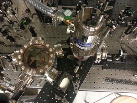
The photograph below shows the experimental test chamber we used for acceleration.
Results
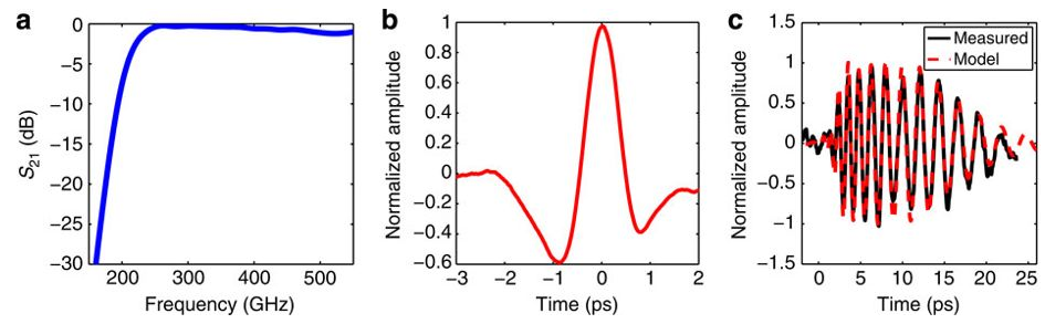
Since the dispersion induces group velocity dispersion, we expect the broadband THz pulse to experience a significant amount of chirp after propagation through the waveguide. The figure below shows the Fourier-limited single-cycle THz pulse before going into the waveguide (middle) and the chirpted THz pulse after propagation (right). Notice also that low frequencies of the pulse below 0.25 are attentuated (left).
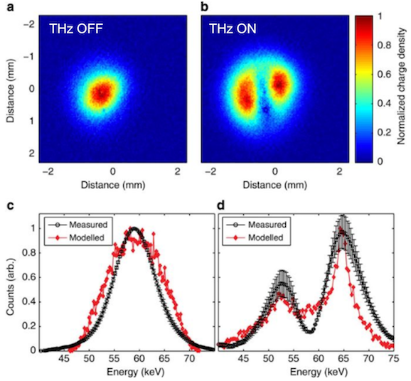
Evidence of electron acceleration is shown below. A steering dipole followed by a multi-channel plate (MCP) is used to spectrally characterize the electron beam after it passes through the THz waveguide. The electron beam image on the MCP is an angularly dispersed image of the beam. When the THz is off, the beam is Gaussian distributed, benchmarking the baseline spectrum. When the THz is turned on, we observe two distinct modes, one containing the electrons which are accelerated and one which contains the electrons which are decelerated. The reason for this is due to the fact that the electron pulse is about 350 fs taking up a significant fraction of the THz cycle. This can be straightforwardly avoided by using a shorter phototriggering pulse. At the optimum delay, we achieved about twice as many electrons accelerated as decelerated, with a maximum energy gain of 7 keV. The figure below shows the electron beam and spectrum with THz off (left figures) and THz on (right figures).
Conclusion
Shrinking billion dollar, mile-long accelerator facilities into a handheld device is one of the great moonshot ideas of the decade. Our THz-driven linac the potential of laser-based techniques to achieve this goal.